
[DB] E-R Model
The entity-relationship (E-R) data model models an enterprise as a collection of entities and relationships that represents the overall logical structure of a database.
-
Entity: a “thing” or “object” in the enterprise that is distinguishable from other objects, which is described by a set of attributes
- e.g.
personwith itsperson_idin a university
- e.g.
-
Relationship: an association among several entities
- e.g.
advisorrelation that associates instructor Katz with student Shankar
- e.g.
The E-R model also has an associated diagrammatic representation called the E-R diagram, which can express the overall logical structure of a database graphically.
※ Note
There is no universal standard for E-R diagram notation, and different books and ER diagram software use different notations. In this post, we follow the notation in the reference textbook, which is close to the UML diagram; we do not use another popular notation, called Chen’s notation.
Basic Components
The E-R data model employs three basic components:
- Entity set
- Relationship set
- Attribute (E-R)
Entity Set
- An entity is an object that exists and is distinguishable from other objects.
- e.g., specific person, company
- An entity set is a set of entities of the same type that share the same properties.
- e.g., set of all instructors, students
- An entity is represented by a set of attributes, and each entity has a value for each of its attributes.
- e.g.,
instructor = (ID, name, salary)
- e.g.,
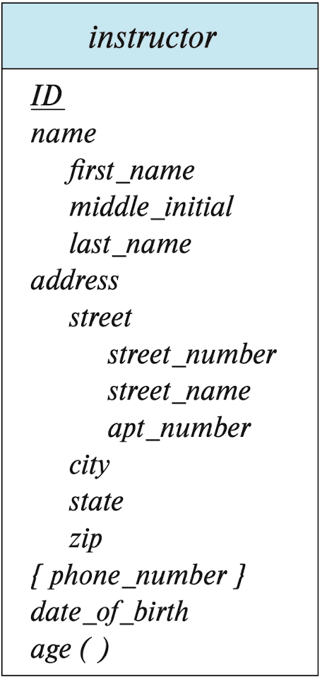
- Entity sets can be represented graphically as follows:
- rectangles represent entity sets
- attributes are listed inside an entity rectangle
- underline indicates the primary key attributes
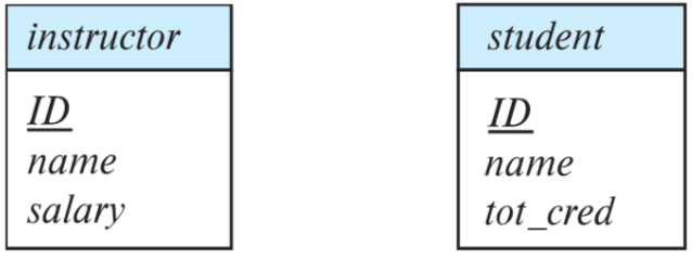
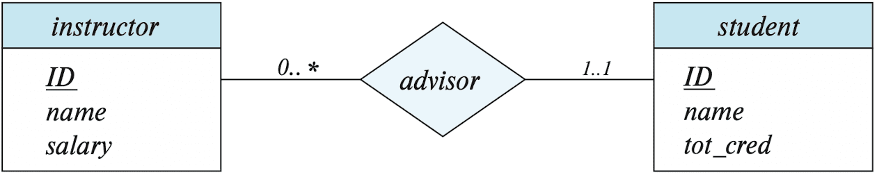
instructor and student (Silberschatz et al.)
Relationship set
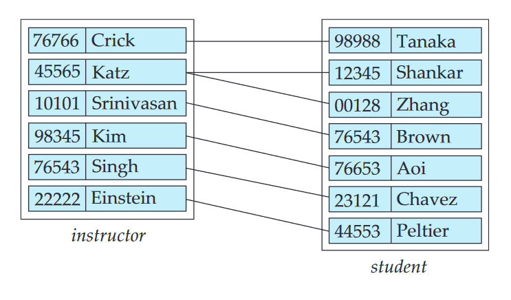
- A relationship is an association among several entities.
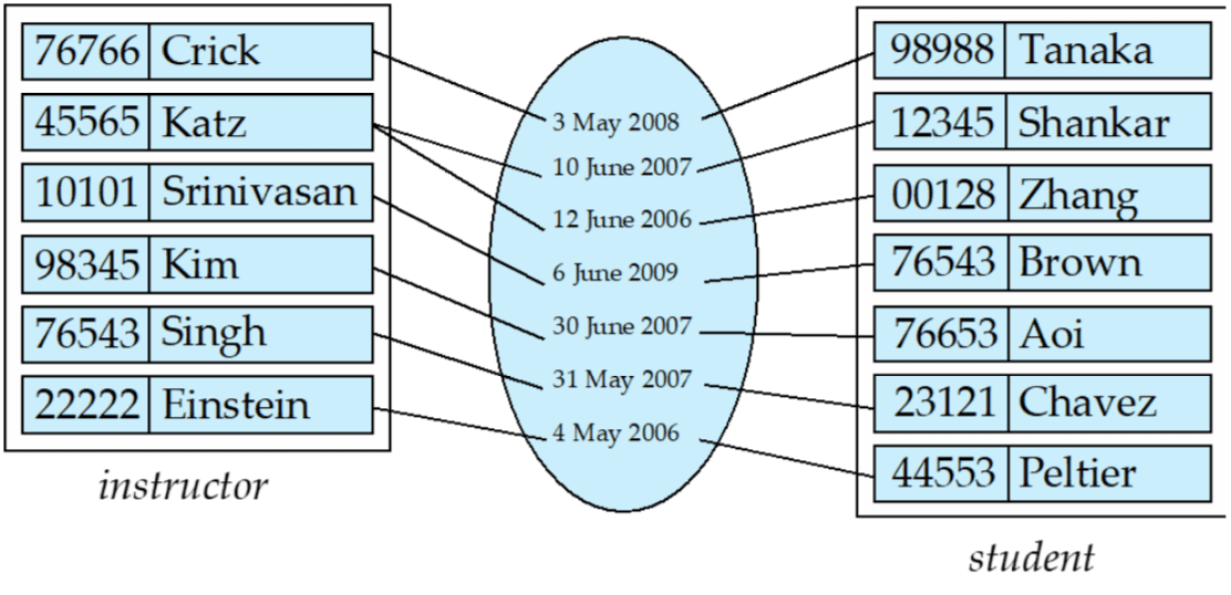
- e.g. advisor that associates instructor Katz with student Shankar
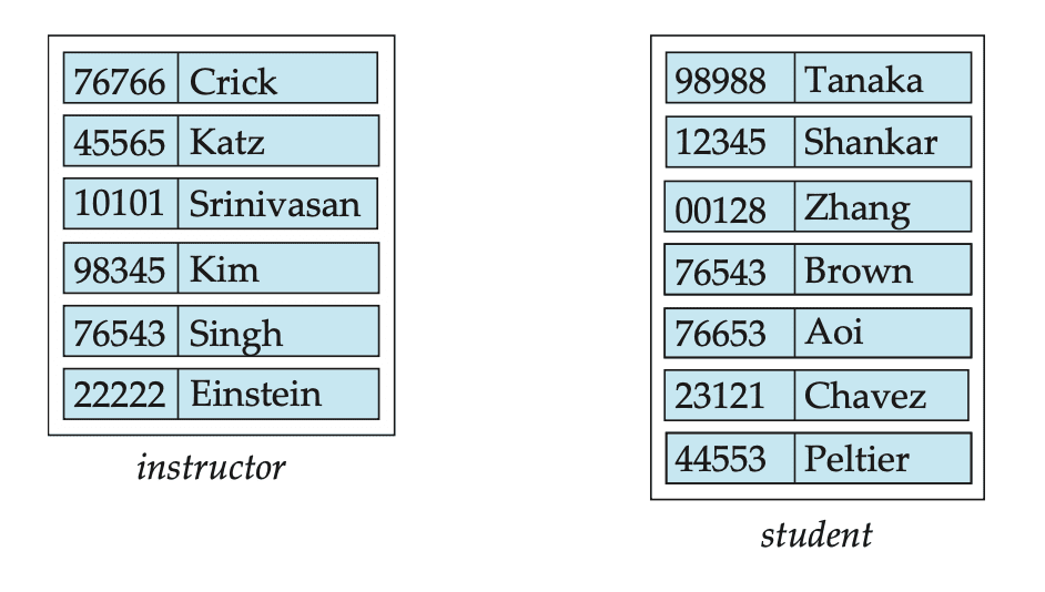
- A relationship instance in an E-R schema represents an association between the named entities in the real-world enterprise that is being modeled.
- e.g. the individual instructor entity Katz, who has instructor ID 45565, and the student entity Shankar, who has student ID 12345
- A relationship set is a set of relationships of the same type. It is a mathematical relation on $n \geq 2$ entity sets that are not necessarily distinct.
- If $E_1, \cdots, E_n$ are entity sets and $(e_1, \cdots, e_n)$ is a relationship instance, then a relationship set $R$ is a subset of
- e.g.
(student_id = 12, instructor_id = 34) ∈ advisor - The entity sets $E_1, \cdots, E_n$ are said to participate in the relationship set $R$.
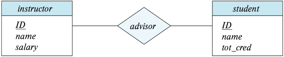
- In ER diagram, diamonds represent relationship sets:
- The function that an entity plays in a relationship is called that entity’s role. Each occurrence of an entity set plays a role in the relationship.
- e.g. in
courseentities, one course is a prerequisite for another course, characterized by(course_id, prereq_id) - Since entity sets participating in a relationship set are generally distinct, roles are implicit and are not usually specified.
- But in some scenarios, e.g. the entity sets of a relationship set are not distinct, they are useful when the meaning of a relationship needs clarification.
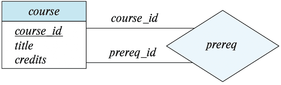
$\mathbf{Fig\ 4.}$ E-R diagram showing relationship set with role indicator (Silberschatz et al.) - e.g. in
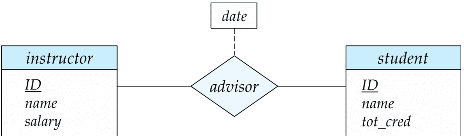
- An relationship may also have attributes called descriptive attirbutes that are associated with a relationship set.
- e.g. the advisor relationship set between entity sets instructor and student may have the attribute date which tracks when the student started being associated with the advisor
- In ER diagram, represented with a dashed line to the diamond of relationship set
Nonbinary relationship sets
- The number of entity sets that participate in a relationship set is the degree of the relationship set.
- A binary set relationship set is of degree 2.
- e.g. takes relationship between student and section.
- A ternary set relationship set is of degree 3.
- e.g. proj_guide relationship that represents a particular student is guided by a particular in- structor on a particular project, between instructor, student, and project
- A binary set relationship set is of degree 2.
Attributes
- An attribute of an entity set is a function that maps from the entity set into a domain.
- A set of permitted values for each attribute is called domain or value set.
- Since an entity set may have several attributes, each entity can be described by a set of
(attribute, data_value)pairs, one pair for each attribute of the entity set.
- An attribute, as used in the E-R model, can be characterised by the following attribute types.
-
Simple / Composite
-
Simple attributes are not divided into subparts
- e.g.
street,city,state, andpostal_code
- e.g.
-
Composite attributes can be divided into subparts.
- e.g.
address
- e.g.
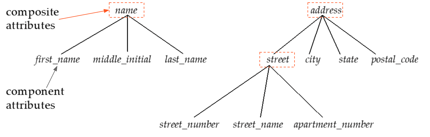
$\mathbf{Fig\ 7.}$ Composite Attributes (Silberschatz et al.) -
Simple attributes are not divided into subparts
-
Single-valued / Multivalued
-
Single-valued attributes have a single value for a particular entity.
- e.g.
instructor_id
- e.g.
-
Multi-valued attributes have a set of values for a specific entity.
- e.g.
phone_numbers(an instructor may have two phone numbers)
- e.g.
-
Single-valued attributes have a single value for a particular entity.
-
Derived
- The value of derived attributes can be derived from the values of other related attributes or entities.
- e.g.
age: we can calculate age fromdate_of _birthand the current date.
- e.g.
- The value of derived attributes can be derived from the values of other related attributes or entities.
-
Simple / Composite
- An attribute takes a null value when an entity does not have a value for it.
Constraints
An E-R enterprise schema may define certain constraints to which the contents of a database must conform.
Mapping Cardinality Constraints
-
Mapping cardinality expresses the number of entities to which another entity can be associated via a relationship set. It is most useful in describing binary relationship sets.
-
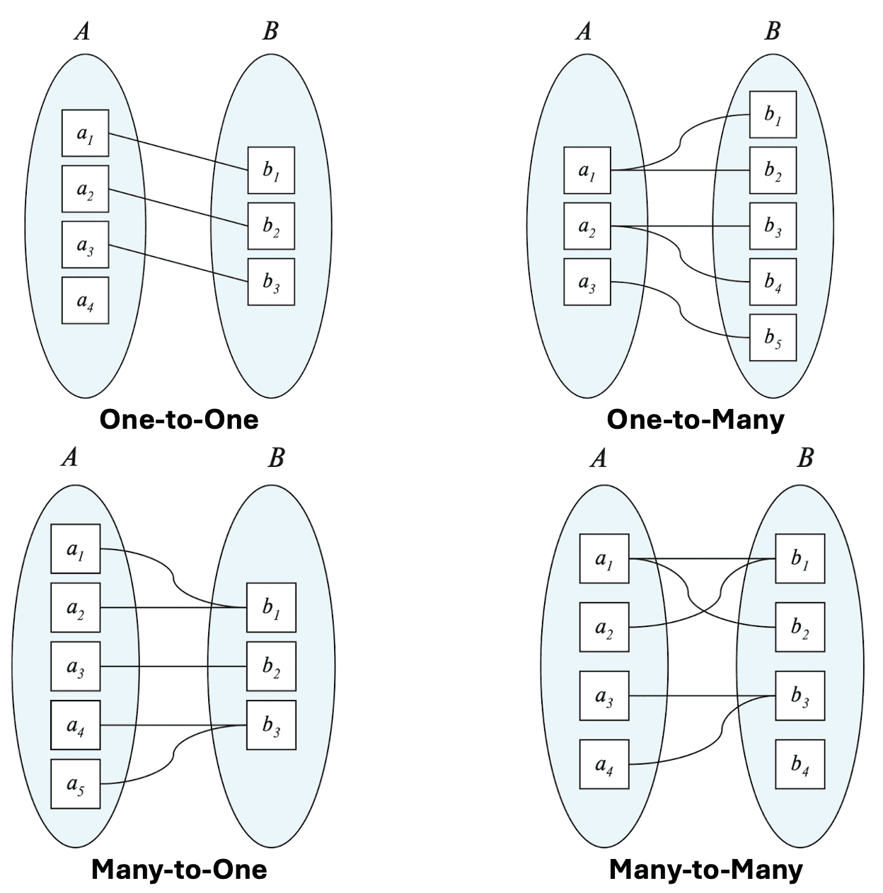
For a binary relationship set $R$ between entity sets $A$ and $B$, the mapping cardinality must be one of the following:
-
One-to-one
- An entity in $A$ is associated with at most one entity in $B$, and vice versa.
-
One-to-many
- An entity in $A$ is associated with any number (zero or more) of entities in $B$. An entity in $B$ can be associated with at most one entity in $A$.
-
Many-to-one
- An entity in $A$ can be associated with at most one entity in $B$. An entity in $B$ is associated with any number (zero or more) of entities in $A$.
-
Many-to-many
- An entity in $A$ is associated with any number (zero or more) of entities in $B$, and vice versa.
-
One-to-one
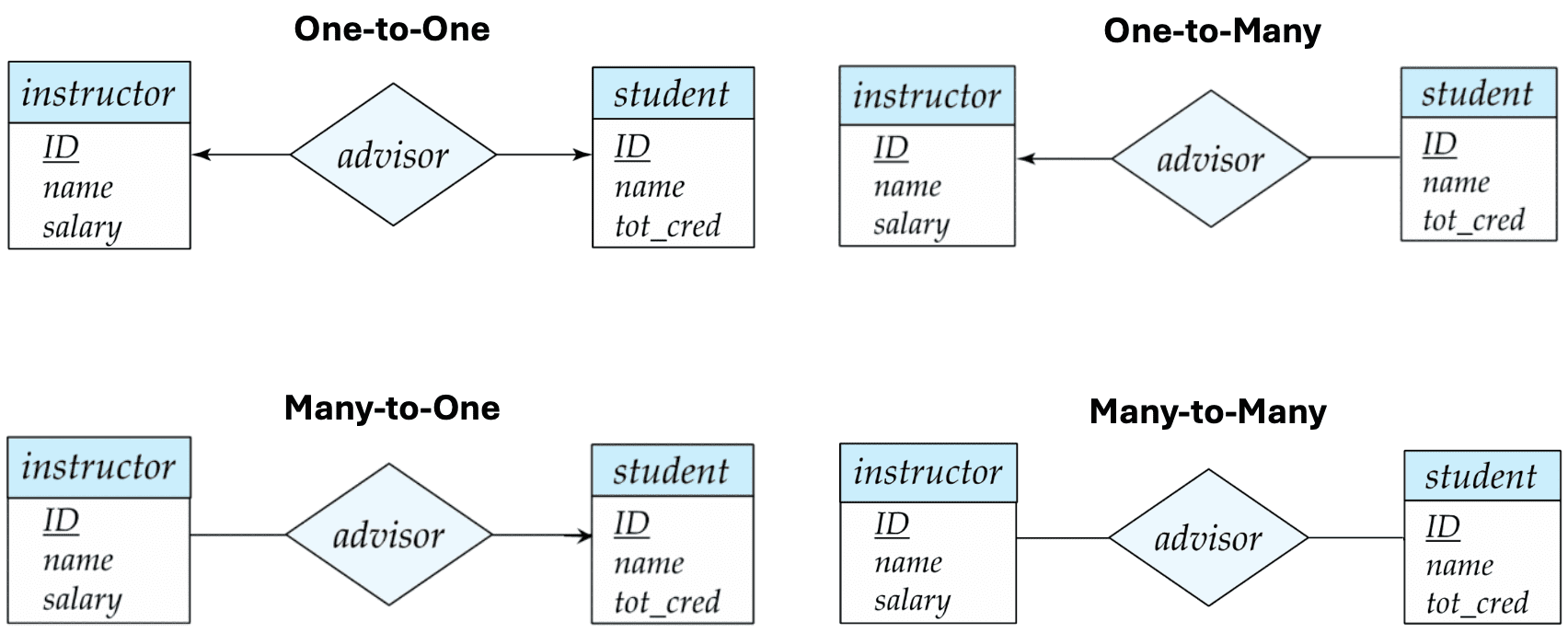
- In ER diagram, between the relationship set and the entity set, we express cardinality constraints by drawing either
- directed line ($\rightarrow$), signifying “one” or
- undirected line (⎯⎯⎯⎯), signifying “many”
Participation Constraints
Let $E$ be an entity set and $R$ be a relationship set.
-
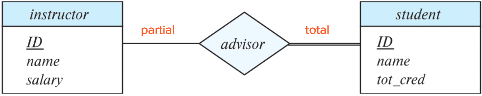
Total participation
- The participation of $E$ in $R$ is said to be total if every entity in $E$ participates in at least one relationship of $R$.
- e.g. every student must have at least one advisor
-
Partial participation
- The participation of $E$ in $R$ is said to be partial if only some entities in $E$ participate in relationships in $R$.
- In ER diagram, total participation of an entity in a relationship set is represented using double lines.
Maximum/Minimum Cardinality Constraints
- A line in ER diagram may have an associated minimum and maximum cardinality, shown in the form $\ell .. h$, where $\ell$ is the minimum and $h$ the maximum cardinality
- A minimum value of $1$ indicates total participation
- A maximum value of $1$ indicates that the entity participates in at most one relationship
- A maximum value of $*$ indicates no limit
Primary Key
Primary keys provide a way to specify how entities and relationships are distinguished. We will consider the primary keys for the followings:
- Weak entity sets
- Entity sets
- Relationship sets
Entity Sets
- By definition, individual entities are distinct. However, from a database perspective, the differences among them must be expressed in terms of their attributes.
- Therefore, the values of the attribute values of an entity must be such that they can uniquely identify the entity.
- The concepts of superkey, candidate key, and primary key are applicable to entity sets just as they are applicable to relation schemas.
Relationships
- To distinguish among the various relationships of a relationship set, the individual primary keys of the entities in the relationship set are used.
- Let $R$ be a relationship set involving entity sets $E_1, \cdots, E_n$.
- Let \(A= \left\{ a_1, \cdots, a_m \right\}\) be the set of attributes assoiciated with $R$, which may be $\varnothing$.
- Then, the primary key for $R$ consists of the union of the primary keys of the entity sets $E_1, \cdots, E_n$, and also is own attributes $A$.
-
That is, the following set of attributes describes an individual relationship in set of for $R$:
\[\left(\bigcup_{i=1}^n \text { primary-key }\left(E_i\right)\right) \cup A\] -
A relationship set is a set of relationship instances, and each instance is uniquely identified by the entities that participate in it. Thus the following set of attributes forms a super key for $R$:
\[\bigcup_{i=1}^n \text { primary-key }\left(E_i\right)\]
-
The choice of the primary key for a relationship set depends on the mapping cardinality of the relationship set.
- Many-to-many: the above union of the primary keys is a minimal superkey and is chosen as the primary key.
- One-to-many, Many-to-one: the primary key of the “many” side is a minimal superkey and is used as the primary key
- One-to-one: the primary key of either one of the participating entity sets forms a minimal superkey, and either one can be chosen as the primary key
Weak Entity Sets
Motivation
- In some scenarios, the primary key of an entity in a relationship is redundant when describing the relationship.
- e.g. a relationship set
sec_coursebetweensection, that already has an attributecourse_id, andcourse
- e.g. a relationship set
- In this case, an alternative way to deal with this redundancy is to not store the redundant attribute in the entity.
- e.g. in
sec_courseonly store the remainingsec_id,year, andsemester. - However, these are not enough to identify a particular
sectionentity uniquely.
- e.g. in
Description
- A weak entity is one whose existence is dependent on another entity, called its identifying entity.
- e.g.
sectionof the course can be opened only ifcourseexists - The identifying entity set is said to own the weak entity set.
- It is existence dependent; every weak entity must be associated with an identifying entity.
- e.g.
- An entity set that is not a weak entity set is termed a strong entity set.
- Instead of associating a primary key with a weak entity, we use the identifying entity, along with extra attributes called a discriminator or partial key to uniquely identify a weak entity.
- The relationship associating the weak entity set with the identifying entity set is called the identifying relationship.
- It is many-to-one from the weak entity set to the identifying entity set, and the participation of the weak entity set in the relationship is always total.
- A weak entity set can participate in relationships other than the identifying relationship.
- e.g.
sectionentity could participate in a relationship with thetime_slotentity set, identifying the time when a particular class section meets. - In this case, a weak entity set may participate as owner in an identifying relationship with another weak entity set.
- e.g.
- It is also possible to have a weak entity set with more than one identifying entity set.
- The primary key of the weak entity set would consist of the union of the primary keys of the identifying entity sets, plus the discriminator of the weak entity set.
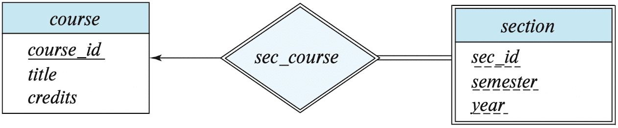
- In ER diagrams, a weak entity set is depicted via a double rectangle
- We underline the discriminator of a weak entity set with a dashed line
- The relationship set connecting the weak entity set to the identifying strong entity set is depicted by a double diamond
Examples
- The relationship
sec_courseis the identifying relationship- the identifying entity set for
sectioniscourse - the primary key of
sectionis formed by the primary key of the identifying entity setcourseplus the discriminator of the weak entity set. - thus the primary key is
course_id,sec_id,year, andsemester.
- the identifying entity set for
- The existence of
roomsis entirely dependent on the existence of ahotel- Thus,
roomcan be seen as the weak entity of thehotel
- Thus,
- The
bank_accountof a particularbankhas no existence if thebankdoesn’t exist anymore - A
companymay store the information ofdependents(parents, children, spouse) of anemployee, but thedependentsdon’t have existence without the employee.- A
dependentwill be a weak entity, and an employee will be the identifying entity fordependent
- A
Redundant Attributes
- Once the entities and their corresponding attributes are chosen, the relationship sets among the various entities are formed.
- Suppose we have two entity sets:
-
student, with attributesID,name,tot_cred,dept_name -
department, with attributesdept_name,building,budget
-
- We model the fact that each student has an associated
departmentusing a relationship setstud_dept - The attribute
dept_namein student replicates information present in the relationship and is therefore redundant and needs to be removed- But, when we create a relational schema from the E-R diagram, the attribute
dept_namegets added to the relationinstructor, but only if each instructor has at most one associated department. - If an instructor has more than one associated department, the relationship between instructors and departments is recorded in a separate relation
inst_dept.
- But, when we create a relational schema from the E-R diagram, the attribute
Reduction to Relational Schema
Entity sets and relationship sets can be expressed uniformly as relation schemas that represent the contents of the database. A database which conforms to an ER diagram can be represented by a collection of schemas. For each entity set and relationship set, there is a unique schema that is assigned the name of the corresponding entity set or relationship set. Each schema has a number of columns (generally corresponding to attributes), which have unique names.
Representation of Entity Sets
- A strong entity set reduces to a schema with the same attributes
- e.g.,
student (ID, name, tot_cred)
- e.g.,
- A weak entity set becomes a table that includes a column for the primary key of the identifying strong entity set
- e.g.,
section (course_id, sec_id, semester, year)
- e.g.,
-
Composite attributes are flattened out by creating a separate attribute for each component attribute.
- e.g., with composite attribute
namewith component attributesfirst_name, andlast_name
- e.g., with composite attribute
- A multi-valued attribute $M$ of an entity $E$ is represented by a separate schema $EM$.
- The schema $EM$ has attributes corresponding to the primary key of $E$, and an attribute corresponding to the multi-valued attribute $M$.
- e.g., Multi-valued attribute
phone_numberofinstructoris represented byinst-phone(ID, phone_number)
- e.g., Multi-valued attribute
- And each value of the multi-valued attribute maps to a separate tuple of the relation on the schema $EM$.
- The schema $EM$ has attributes corresponding to the primary key of $E$, and an attribute corresponding to the multi-valued attribute $M$.
Representation of Relationship Sets
- A many-to-many relationship is represented as a schema with attributes for the primary keys of the two participating entity sets, and any descriptive attributes of the relationship set.
- e.g., Schema for a relationship set
advisorbetweenstudentandinstructorisadvisor(student_id, instructor_id);
- e.g., Schema for a relationship set
-
Many-to-one and one-to-many relationship sets that are total on the many-side can be represented by adding an extra attribute to the ‘many’ side, containing the primary keys of the ‘one’ side.
- e.g., Instead of creating a new schema for a relationship set
inst-deptbetweeninstructoranddepartmentwith many-to-one mapping, add an attributedept_nameto the schema arising from the entity setinstructor. - e.g.
stud_dept$\Rightarrow$student(ID, name, dept_name, credits) - If the participation if partial on the ‘many’ side, this could result in
NULLvalues.
- e.g., Instead of creating a new schema for a relationship set
- A one-to-one relationship sets, either side can be chosen to act as the ‘many’ side.
- An extra attribute can be added to either of the tables corresponding to the two entity sets
Redundancy of Schemas
- The schema corresponding to a relationship set linking a weak entity set to its identifying strong entity set is redundant.
- e.g., The
sectionschema already contains the attributes that would appear in thesec-courseschema, thussec-courseis redundant.
- e.g., The
- Hence it does not need to be present in a relational database design based upon an E-R diagram.
Extended E-R features
Although the basic E-R concepts can model most database features, some aspects of a database may be more aptly expressed by certain extensions to the basic E-R model.
Specialization
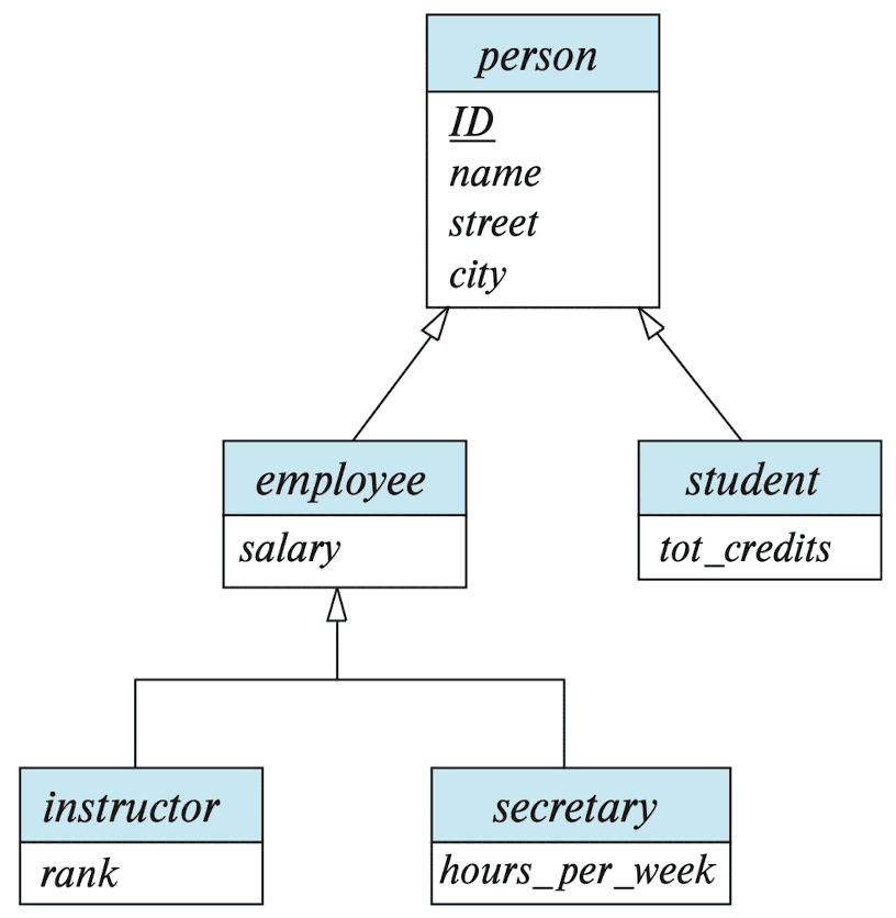
In top-down design process, an entity set may include sub-grouping of entities that are distinct in some way from other entities in the set. The process of designating subgroups within an entity set is called specialization.
- e.g., the specialization of
personallows us to distinguish among person entities according to whether they correspond toemployeeorstudent.
These subgroupings become lower-level entity sets that have attributes or participate in relationships that do not apply to the higher-level entity set. Hence, the specialization relationship may also be referred to as a superclass-subclass relationship.
Representation of Specializations
In terms of an E-R diagram, it is depicted by a hollow arrow-head pointing from the specialized entity to the other entity. We refer to this relationship as the IS A relationship, which stands for “is a” and represents, for example, that instructor “is a” employee.
The way we depict specialization in an E-R diagram depends on whether an entity may belong to multiple specialized entity sets (overlapping specialization) or if it must belong to at most one specialized entity set (disjoint specialization).
Method 1
- Form a schema for the higher level entity.
- Form a schema for each of the lower level entity set, and include the primary key of the higher level entity set and local attributes.
e.g.,
- Drawbacks: Accessing information about an lower level entity requires accessing two relations (the one corresponding to the lower level schema, and the one corresponding to the higher level schema).
Method 2
- Form a schema for each entity set with all local and inherited attributes.
e.g.,
-
Drawbacks: Some attributes may be stored redundantly for entities that belongs to two or more specialized entity sets.
- e.g.
name,street, andcitymay be stored redundantly for people who are bothstudentsandemployees
- e.g.
Generalization
Conversely, generalization is a containment relationship that exists between a higher-level entity set and one or more lower-level entity sets. This is a bottom-up design process, in which multiple entity sets are synthesised into a higher-level entity set on the basis of common features.
Specialization and generalization are simple inversions of each other and represented in an ER diagram in the same way; thus these terms are used interchangeably.
Constraints on Specializations/Generalizations
To model an enterprise more accurately, the database designer may choose to place certain constraints on a particular generalization and specialization.
Disjoint/Overlapping Constraint
One type of constraint on specialization specifies whether a specialization is disjoint or overlapping.
-
Disjoint specialization
- A disjoint constraint requires that an entity belong to at most one lower-level entity set.
- e.g.
instructorandsecretary
-
Overlapping specialization
- An overlapping constraint requires that an entity may belong to multiple lower-level entity sets within a single specialization.
- e.g.
employeeandstudent
Completeness Constraint
The completeness constraint specifies whether or not an entity in the higher-level entity set must belong to at least one of the lower-level entity sets within the generalization.
-
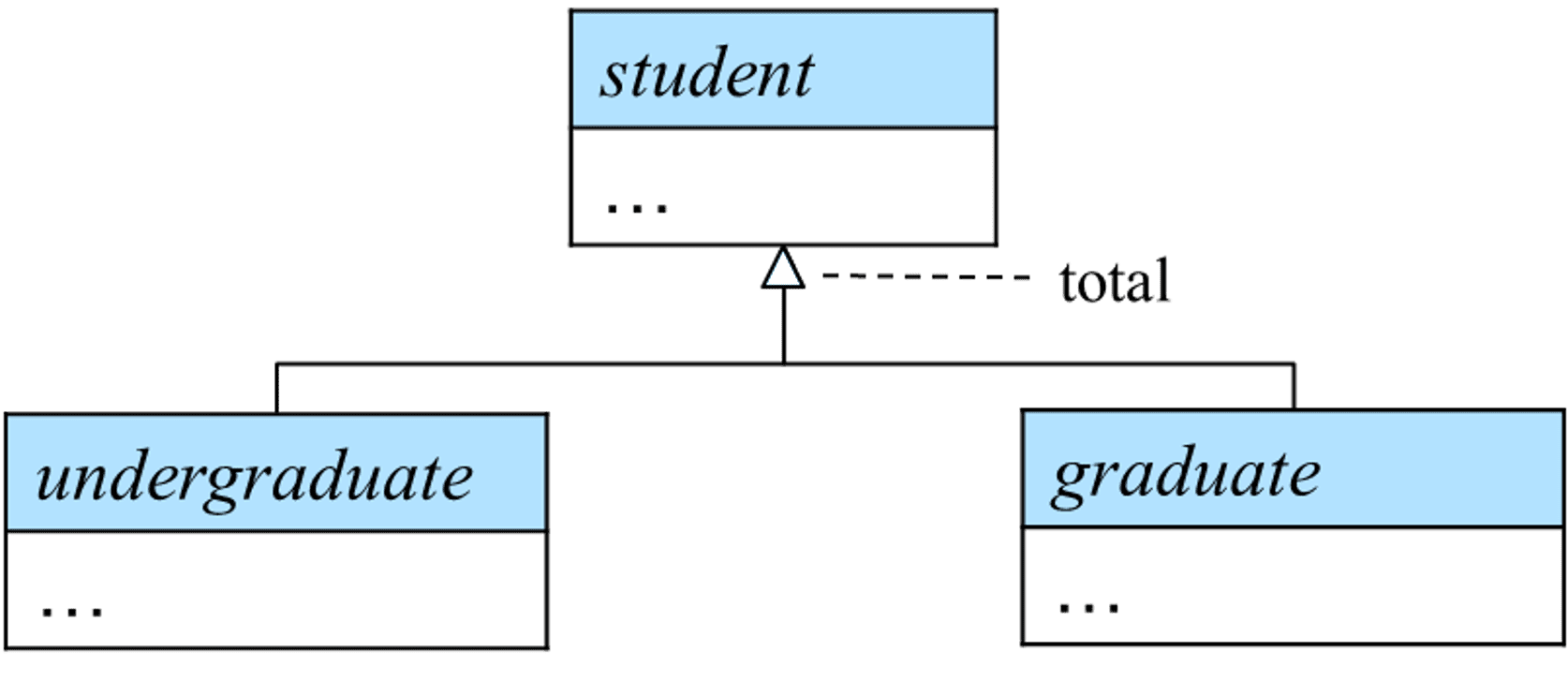
Total specialization/generalization
- Each higher-level entity must belong to one of the lower-level entity sets;
- We can specify it in an ER diagram by adding the keyword “total” in the diagram and drawing a dashed line from the keyword to the corresponding hollow arrow-head to which it applies or to the set of hollow arrow-heads to which it applies.
-
Partial specialization/generalization
- Some higher-level entities may not belong to any lower-level entity sets;
Aggregation
- Limitation: E-R model cannot express relationships among relationships.
-
Example
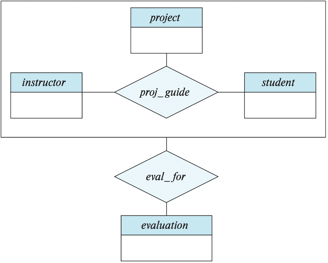
- consider the ternary relationship
proj_guide, which we saw earlier. - suppose we want to record evaluations of a student by a guide on project, in
eval_for. - Then there is redundancy between
eval_forandproj_guideoverlapped;- every
instructor,student,projectcombination ineval_formust also be inproj_guide.
- every
- consider the ternary relationship
Aggregation is an abstraction through which relationships are treated as higher-level entities. By treating relationship as an abstract entity, relationships between relationships can be defined, thereby reducing unnecessary redundancy.
- e.g., regard
proj_guideas a higher-level entity set, then create a binary relationshipeval_forbetweenproj_guideandevaluation;
Representation of Aggregations
To represent aggregation, create a schema containing
- The primary key of the aggregated relationship
- The primary key of the associated entity set
- Any descriptive attributes, if exists
In our example, the schema eval_for is eval_for (s_ID, project_id, i_ID, evaluation_id).
Note that the schema proj_guide is redundant (thus can be removed), provided that we are allowed to store NULL values for the score attribute in evaluation.
-
evaluation (id, score):scorecould beNULLif the corresponding(instructor, student, project)combination was not evaluated;
E-R Design Issues
The notions of an entity set and a relationship set are not precise, and it is possible to define a set of entities and the relationships among them in a number of different ways.
Common mistakes in E-R models
- A common mistake when creating E-R models:
- Use of a primary key of an entity set as an attribute of another entity set, instead of using a relationship;
- Use of a relationship with a single-valued attribute in a situation that requires a multi-valued attribute;
- e.g., we can only represent a single assignment for a given student-section pair if we add
assignmentandmarksto the relationshiptake
- e.g., we can only represent a single assignment for a given student-section pair if we add
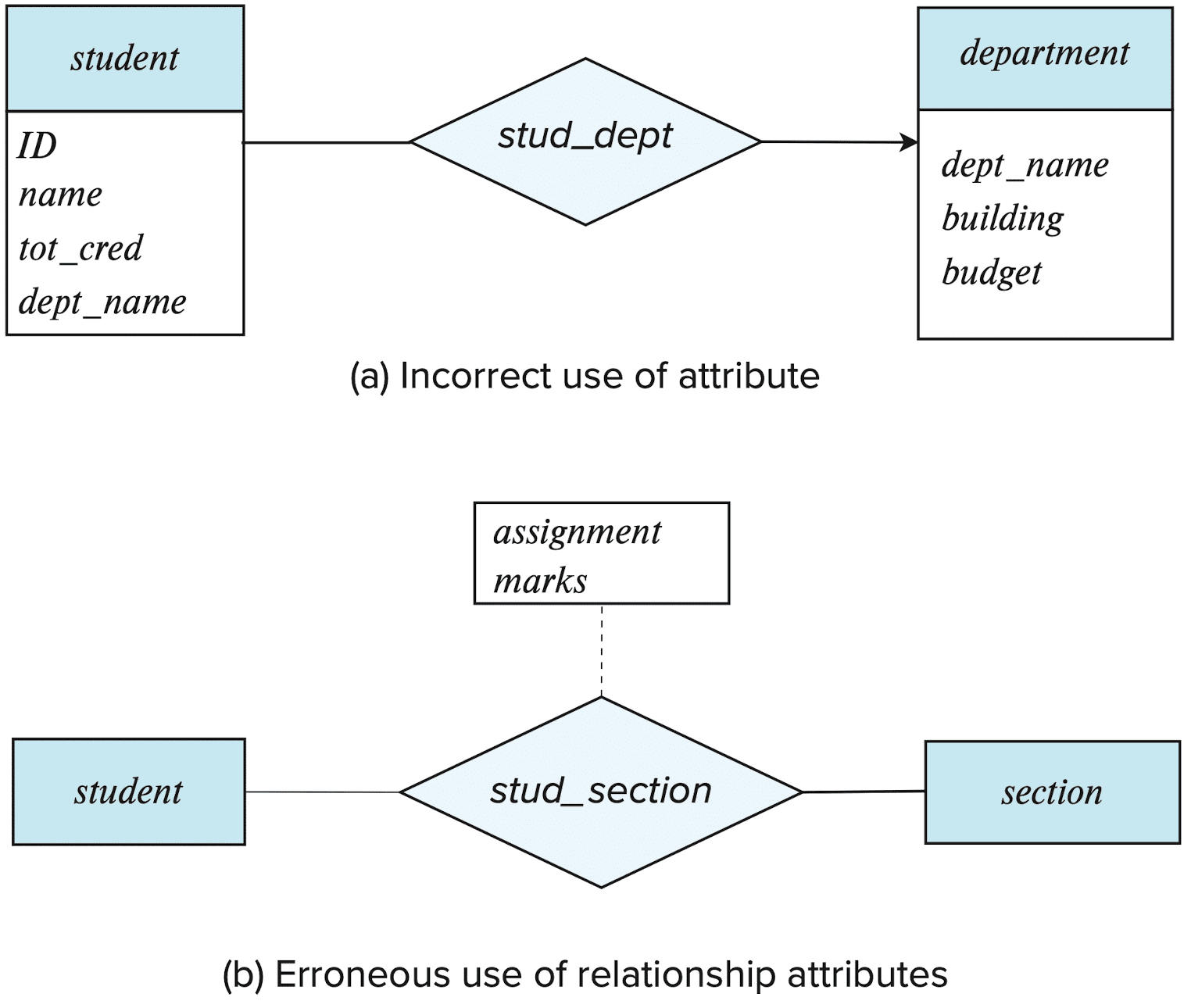
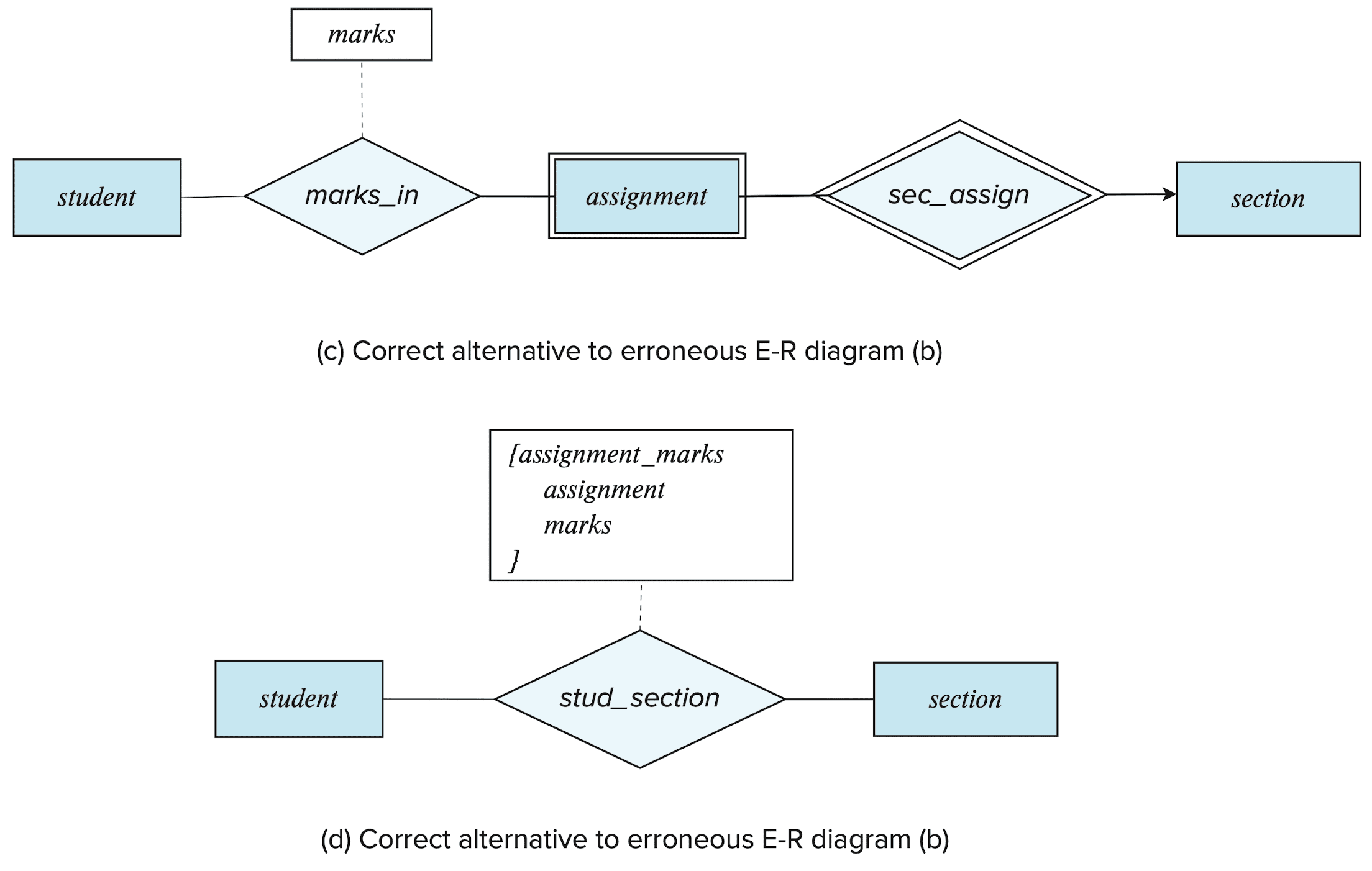
- Possible solutions:
- Use a weak entity set;
- e.g. model
assignmentas a weak entity identified bysection, and to add a relationshipmarksin betweenassignmentandstudent
- e.g. model
- Use a multivalued composite attribute;
- e.g. use
{assignment_marks}totakes, where it has component attributesassignmentandmarks
- e.g. use
- Use a weak entity set;
Entity Sets vs. Attributes
Consider the entity set instructor with the additional attribute phone_number. There are two possible ways to model this as an E-R model:
-
phone_numberis an attribute of an entityinstructor;- i.e. instructors have precisely one phone number each
-
phoneis an entity in its own right with attributesphone_number;- i.e. permits instructors to have several phone numbers (including zero) associated with them
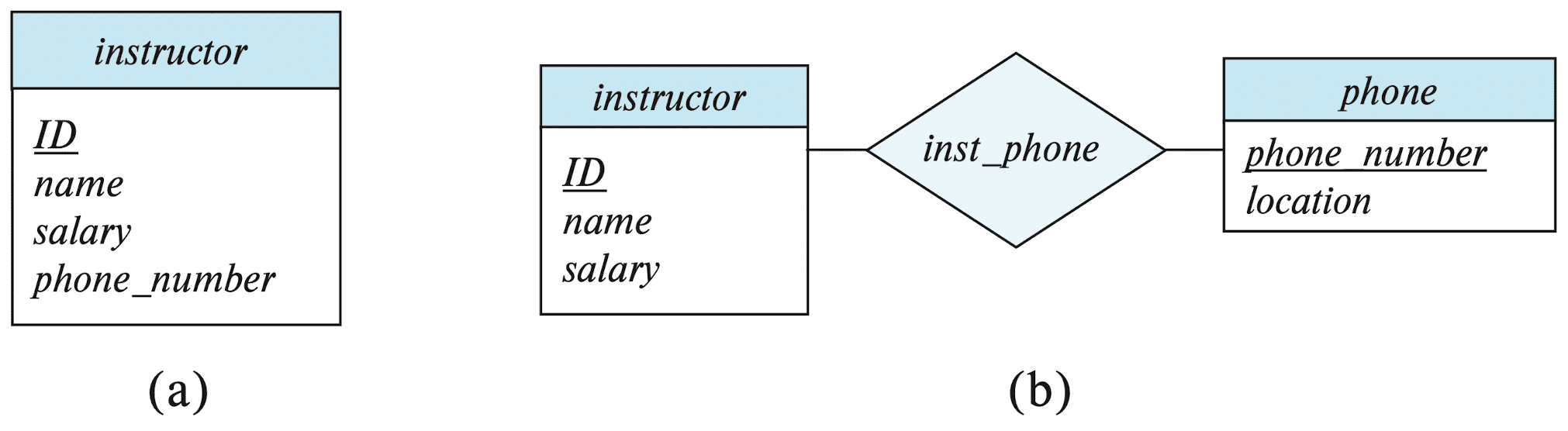
The main difference is that treating a phone as an entity better models a situation where one may want to keep extra information about a phone, such as location, type, or possibly multiple phone_numbers per instructor.
Entity Sets vs. Relationship Sets
Consider the entity sets section and student, and the relationship between them indicating the section(s) that a student takes. There are two possible ways to model this as an E-R model:
- As a relationship set
takes;- e.g. more compact and probably preferable
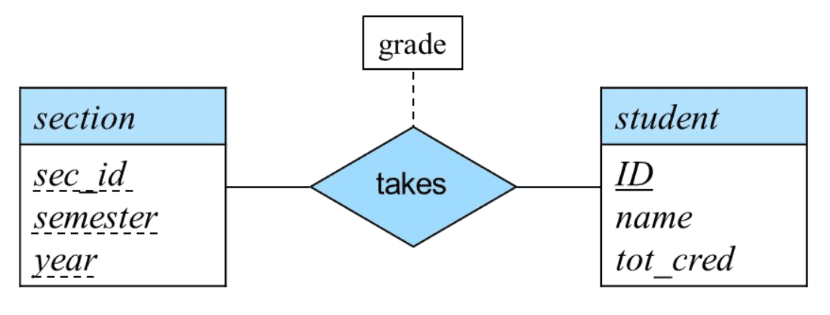
takes relationship set (Silberschatz et al.)
- As an entity set
registration, and two relationship sets betweenregistrationandsectionorstudent;- e.g. if the registrar’s office associates other information with a course-registration record, it might be best to make it an entity in its own right.
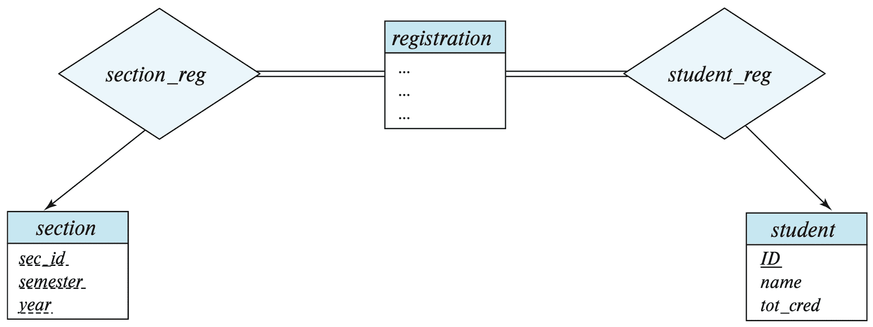
takes by registration and two relationship sets. (Silberschatz et al.)
A possible guideline is to designate a relationship set to describe an action that occurs between entities.
Binary vs. Non-binary Relationships
Although it is possible to replace any non-binary ($n$-ary, $n > 2$) relationship set by a number of distinct binary relationship sets, a $n$-ary relationship sets shows more clearly that several entities participate in a single relationship.
However, some relationships that appear to be non-binary may be better represented using binary relationships.
- e.g. a ternary relationship
parents, relating a child to his/her father and mother, is best replaced by two binary relationships,fatherandmother- Using two binary relationships allows partial information (e.g., only mother being known)
- But there are some relationships that are naturally non-binary
- e.g.,
proj_guide
- e.g.,
Converting Non-binary Relationships
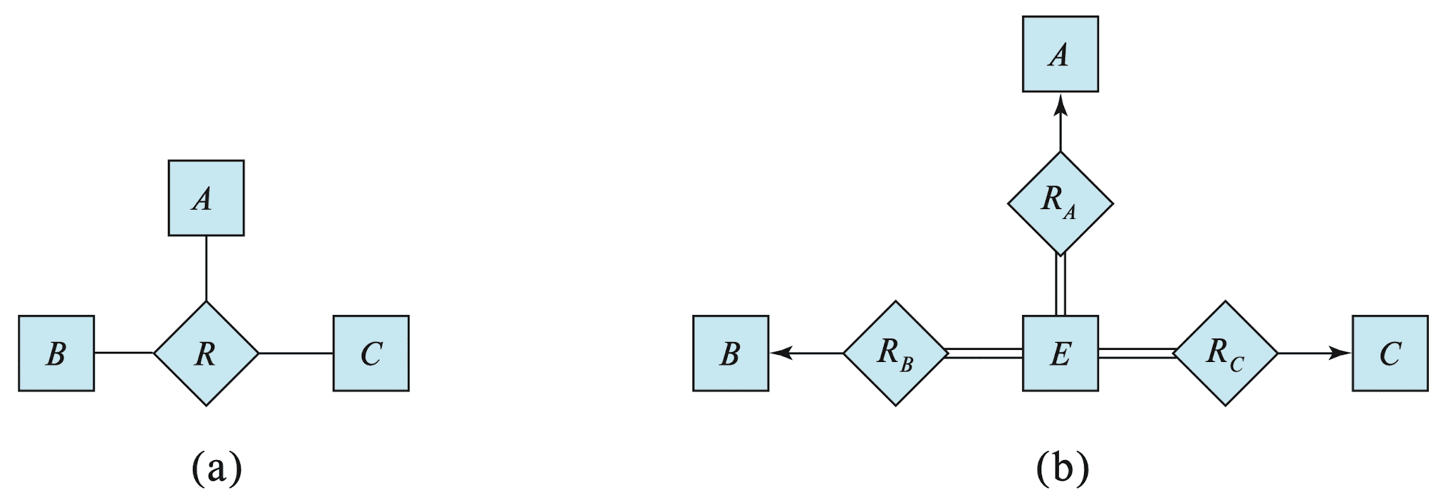
In general, any non-binary relationship can be represented using binary relationships by creating an artificial entity set, and creating an identifying attribute for the artificial entity set to other entity sets participating in the relationship.
- Replace $R$ ($n = 3$) between entity sets $A$, $B$, and $C$ by an entity set $E$ and three relationship sets:
- $R_A$, many-to-one relating $E$ and $A$
- $R_B$, many-to-one relating $E$ and $B$
- $R_C$, many-to-one relating $E$ and $C$
- $E$ is required to have total participation in each of $R_A$, $R_B$, and $R_C$
- Create an identifying attribute for $E$ and add any attributes of $R$ to $E$
- For each relationship $(a_i, b_i, c_i) \in R$,
- create a new entity $e_i$ in the entity set $E$
- add $(e_i , a_i)$ to $R_A$
- add $(e_i , b_i)$ to $R_B$
- add $(e_i , c_i)$ to $R_C$
Thus, conceptually, we can restrict the E-R model to include only binary relationship sets. However, this restriction is not always desirable.
- Creation of new entity sets and attributes increases the complexity of the design and the overall storage requirements;
- An $n$-ary relationship set shows more clearly that several entities participate in a single relationship;
- There may not be a way to translate constraints on the ternary relationship into those on the binary relationships;
- e.g., consider a constraint saying that $R$ is many-to-one from $A$, $B$ to $C$; that is, each pair of entities from $A$ and $B$ is associated with at most one $C$ entity. This constraint cannot be expressed by using cardinality constraints on $R_A$, $R_B$, and $R_C$
- There may be instances in the translated schema that cannot correspond to any instance of the original relationship;
Reference
[1] Silberschatz, Abraham, Henry F. Korth, and Shashank Sudarshan. “Database system concepts.” (2011).
Leave a comment